Preliminary Tutorial - Setting Up a Sandwich Conveyor
Image-Source: Eric Fimbinger
Images already published in various papers (NAFEMS 2019, Quebec, Canada / ICBMH 2019, Gold Coast Australia etc.)
Requirements:
- CAD Data of the conveyor as described below
- ThreeParticle/CAE by Becker3D (becker3d.com)
- BeltConverter and optional PartConverter from this website
- Information on the model parameters to represent the belt/systems behaviour
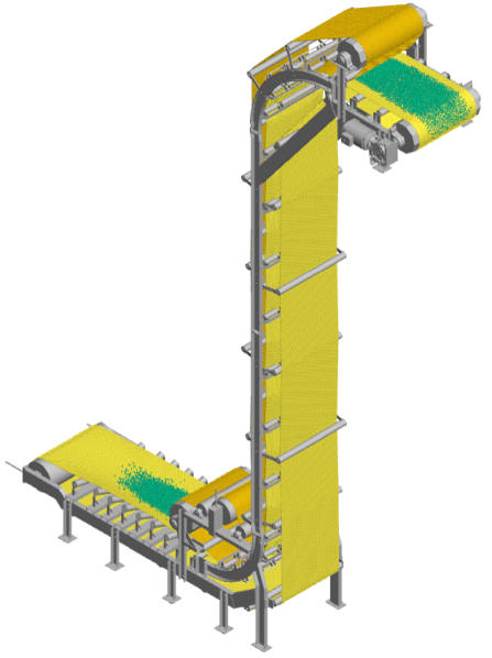
CAD model of the conveyor system in total
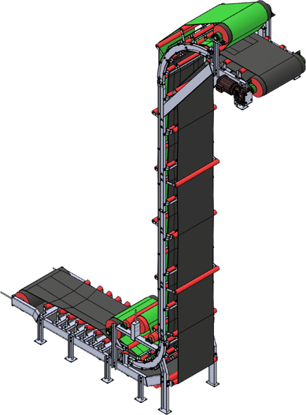
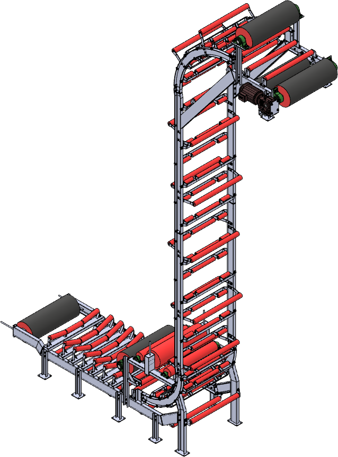
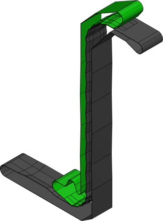
CAD model split into structural parts (left) and belt models (right)
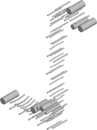
Optional: using the PartConverter for the conversion of cylindrical parts into INP-Format for ThreeParticle/CAE
This is suitable if the system contains lots of idlers and drums; otherwise manual positioning of the cylinders is an alternative option suitable for very small and simple systems.
In the options of the PartConverter the details for the conversion can be set, e.g. if the cylinders should be generated as "parts" or "particles".
(Parts are suitable for cylinders that are single or up to a low amount; particles may be a good option esp. for idlers, that have a lower diameter or a higher amount in the assembly)
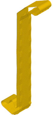
For the conversion of each belt, the CAD model of the belt is of great importance:
The model must represent the "middle" surface of the belt as a single surface model (not volume).
The edges of the belt must be shorter in the surface model than the effective belt surface, because the "edge" particles will be placed with their center exactly on the edge of the model.
Conclusion: belt width CAD model = desired belt with - 1x particle width
The model must not contain small surfaces, such as in small bendings - those small bendings can be replaces by a sharp edge.
Also the model must be either a infinite belt with two edges or a finite belt with four edges.
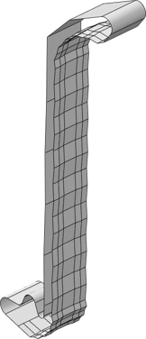
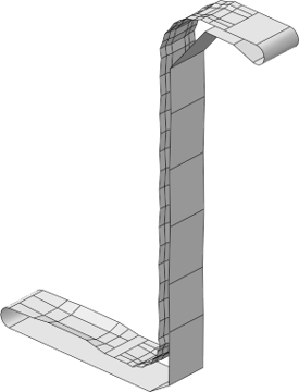
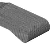
The surface model of the belt must be meshed according to some rules: (Detail of the mesh in the right image)
The mesh represents the setup of the bonded particles, therefore the distances represent the deformed state of the bonded elements.
(E.g. when the belt should be in a state of 2% elongation and should have about 40mm bonding length, the mesh length should be about 40,8mm.)
The mesh must be rectangular in every area of the surface.
After the meshing, the mesh must be exported in a STL file (ASCII, not binary) for the use in the BeltConverter.
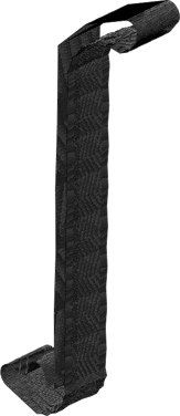
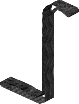
Using the BeltConverter to convert the STL-mesh into a INP-File for the use in ThreeParticle/CAE
In the settings some relevant option have to be set:
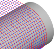
Most important is the belt elongation definition - this sets the bonding element details during the conversion in the two main directions (see detail image on the left).
Also the definition of an initial velocitiy is possible (see detail image on the right).
To define complex behaviour of the belt in different directions/areas of the belt, a fibred structure generation is possible using the naming options.
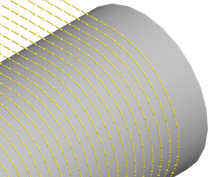
In ThreeParticle/CAE the particles/bondings/interactions of the belt must be defined
An option to set up the belt with a smoothened surface is the use of box (cuboidal) particles with rounded edges (image left).
The whole belt will be represented with these defined particles - and if chosen: also as a fibred structure.

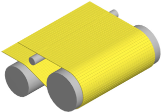
In ThreeParticle/CAE the whole belt models imported will look like this
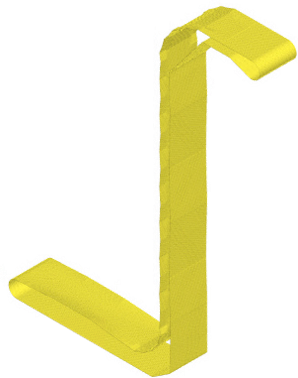
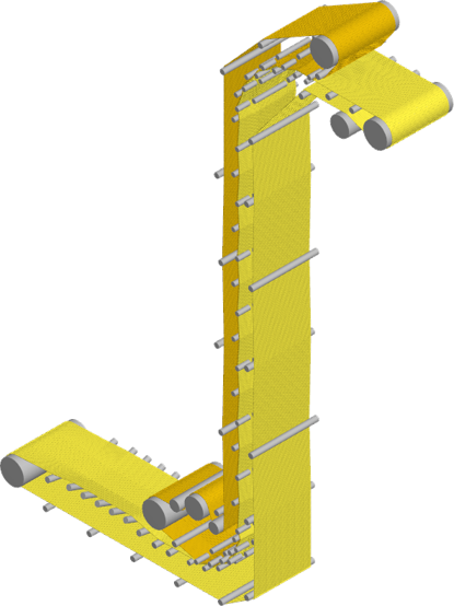
Assembling the whole model in ThreeParticle/CAE
Import (or alternatively manual set up) the cylindrical parts and also import the two belt models (INP files).
And define remaining system details, e.g. bulk material settings, interactions, drum movements, multi body systems etc.
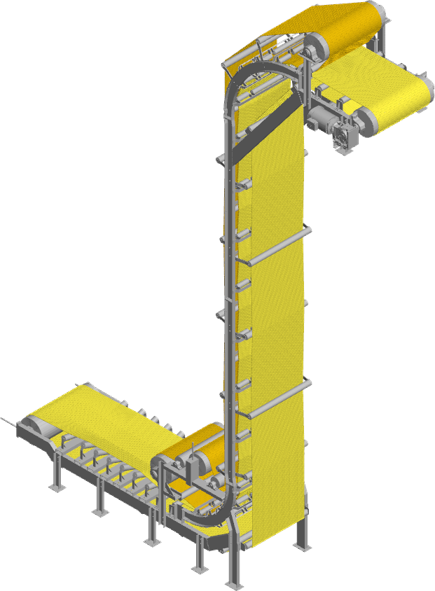
ThreeParticle/CAE supports the visualisation of the systems structure
Import the system structure as a "visual" to visualise the whole conveyor system in the simulation.
Performing the simulation
For more details see also the corresponding publications (papers, presentations etc. as e.g. mentioned above)
or contact the developer Eric Fimbinger (eric@fimbinger.at)


